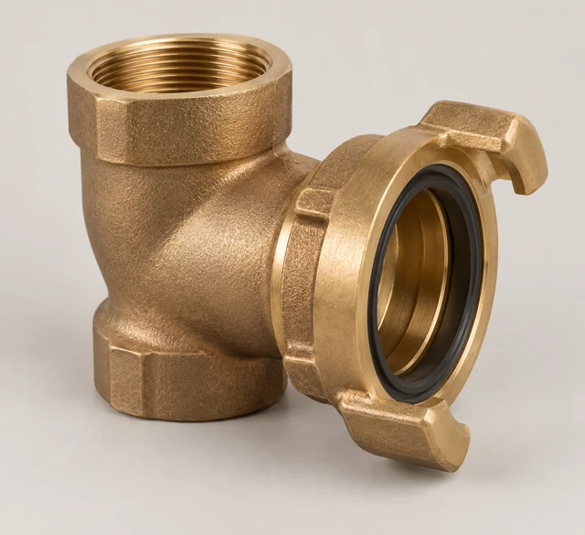
Provides the coupling body and drawing-defined connection or swivel interface.
Manufacturing & delivery form
Cast connection body with thread and seal-face machining; forging routes require separate definition.
Hose threads and NPT/BSP pipe threads are distinct. A complete coupling can contain seals, swivels and other components outside the body scope.
Material candidates
Customer specified
Approved material to be defined
No default copper-casting alloy is established for this component.
Obtain the approved metal, seal and coating specifications from the equipment owner before assessing a manufacturing route.
UNS C83600
Leaded red brass
A candidate for specified cast valve bodies, covers and connection housings.
An application candidate, not a confirmed equipment bill of materials or available Zhiren grade. Do not default to potable-water use.
UNS C87600
Cast copper-silicon alloy
A drawing-led candidate for selected connection and valve components.
Not interchangeable with wrought brass grades. The customer must approve the exact alloy, manufacturing form and service.
Confirm the drawing, actual duty, material standard and manufacturing condition. Material substitutions require customer approval, and supply scope is agreed after component review.
Component RFQ requirements
- Connection standard
- Give the exact hose and pipe interface standards, thread form, direction and mating gauges.
- Body geometry
- Define bore, wall sections, lug or swivel features and approved drawing revision.
- Sealing and assembly
- Identify gasket profile, seal face, retention method and included versus excluded parts.
- Duty and acceptance
- Specify pressure and mechanical requirements, environment, finish and inspection criteria.
- Material and approval
- Confirm casting or forging route, approved alloy, machining state and first-article/traceability records.
Start with your drawing, specified alloy and quantity. Include the required delivery condition and acceptance records so the manufacturing and inspection scope can be reviewed.