COMPONENT REQUIREMENTS

Fire connection elbow / branch body

Define the geometry, material, delivery condition and acceptance criteria for the selected application. Manufacturing scope requires review of the approved drawing and operating requirements.

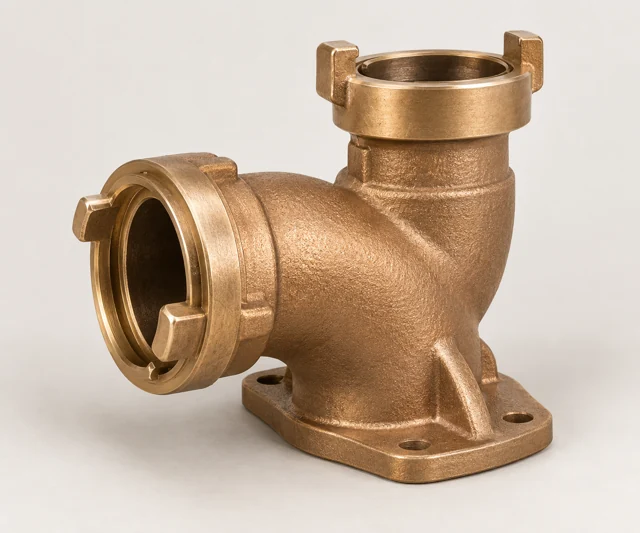
Illustrative Fire connection elbow / branch body
Generated component illustration. It is not a Zhiren product photograph or an engineering drawing; final geometry follows the controlled drawing.
Illustrative Fire connection elbow / branch body
Conceptual part illustration
COMPONENT GUIDE

Fire connection elbow / branch body

Direction-change or branch point in a specified fire-service or test connection

Connects the inlet and outlet passages with drawing-defined orientation and connection geometry.

Manufacturing & delivery form
Complex elbow or branch casting with interface machining.

Different local inlet, outlet and test-connection functions require their own drawings. A cast branch body is not bent copper tube or an entire FDC assembly.

Material candidates

Customer specified Approved material to be defined

No default copper-casting alloy is established for this component.

Obtain the approved metal, seal and coating specifications from the equipment owner before assessing a manufacturing route.

UNS C83600 Leaded red brass

A candidate for specified cast valve bodies, covers and connection housings.

An application candidate, not a confirmed equipment bill of materials or available Zhiren grade. Do not default to potable-water use.

UNS C87600 Cast copper-silicon alloy

A drawing-led candidate for selected connection and valve components.

Not interchangeable with wrought brass grades. The customer must approve the exact alloy, manufacturing form and service.

Confirm the drawing, actual duty, material standard and manufacturing condition. Material substitutions require customer approval, and supply scope is agreed after component review.

Component RFQ requirements

Branch configuration
Provide bores, angles, centre-to-end dimensions, flow direction and approved casting drawing.
Interface standards
Define local hose/pipe connections, sealing arrangement and connection engagement.
Mechanical layout
Identify wall sections, mounting constraints, connection loading and finish requirements.
Pressure acceptance
Specify duty, casting-defect criteria, pressure/leak test and responsible party.
Approved material and form
Confirm alloy, casting versus other route, machining state, revision control and batch records.

Start with your drawing, specified alloy and quantity. Include the required delivery condition and acceptance records so the manufacturing and inspection scope can be reviewed.

Prepare a component enquiry
FURTHER GUIDANCE

Prepare the technical RFQ.

Drawing preparation

Define the delivery scope.

Provide the approved drawing or model, specified material and quantity. Identify the required casting, machining, surface treatment and final equipment validation, with responsibility assigned for each.

Prepare your enquiry