COMPONENT REQUIREMENTS

Slipper pad

Define the geometry, material, delivery condition and acceptance criteria for the selected application. Manufacturing scope requires review of the approved drawing and operating requirements.

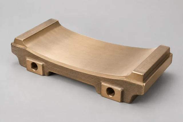
Illustrative Slipper pad
Generated component illustration. It is not a Zhiren product photograph or an engineering drawing; final geometry follows the controlled drawing.
Illustrative Slipper pad
Conceptual part illustration
COMPONENT GUIDE

Slipper pad

Replaceable contact pad in a specified mill sliding or drive interface.

Provides the drawing-defined sliding contact surface between mating parts.

Manufacturing & delivery form
Near-shape casting or plate blank with agreed machining.

Slipper location and geometry depend on the mill design; one illustrative position does not apply to every mill.

Material candidates

UNS C86300 Manganese brass / manganese bronze

Candidate for specified heavily loaded sliding parts and nut blanks.

A high-strength brass family, not tin bronze. Confirm the counterface and lubrication; no universal wear-life claim applies.

UNS C95400 Aluminium bronze

Candidate for drawing-defined loaded sliding and wear components.

Review mating material, lubrication and supply condition. C95400 and C95800 are distinct grades.

Confirm the drawing, actual duty, material standard and manufacturing condition. Material substitutions require customer approval, and supply scope is agreed after component review.

Component RFQ requirements

Pad geometry
Profile, thickness, contact contour and mounting holes.
Mating contact
Counterface material, contact area and required surface finish.
Movement & load
Contact pressure requirement, travel, direction and operating cycle.
Lubrication & temperature
Lubricant, feed features and actual part temperature.
Material & acceptance
Specified alloy and standard, supply condition, drawing revision, quantity, inspection criteria and required records.
Supply form
Near-shape casting or plate blank with agreed machining.
Start with your drawing, specified alloy and quantity. Include the required delivery condition and acceptance records so the manufacturing and inspection scope can be reviewed.

Prepare a component enquiry
FURTHER GUIDANCE

Prepare the technical RFQ.

Drawing preparation

Define the delivery scope.

Provide the approved drawing or model, specified material and quantity. Identify the required casting, machining, surface treatment and final equipment validation, with responsibility assigned for each.

Prepare your enquiry